-
1.
北京科技大学机械工程学院,北京 100083
-
2.
北京睿力恒物流技术股份公司,北京 100080
摘要: 本文运用ADAMS仿真软件建立发动机曲柄连杆机构多刚体动力学模型,并在最大转矩工况和最高转速工况下进行仿真分析。分析表明连杆构件在运动过程中所承受的最大压缩载荷和最大拉伸载荷与理论值相比误差均小于5%,证明仿真方法合理,同时为连杆的结构设计和改进设计提供了理论依据。通过实践教学与现代设计手段相结合可以使学生对机器机构了解的更加透彻和深入,发动机拆装实践使学生获取产品直观真实的工程机构知识。
本研究以发动机曲柄连杆机构为研究对象,基于多刚体动力学分析理论,建立发动机曲柄连杆机构多刚体动力学模型[1-2]。计算了发动机连杆在最大转矩工况和最大转速工况下连杆的动态应力,并与理论计算值对比,证明了仿真方法合理性[3]。
1. 曲柄连杆机构多刚体动力学分析
以发动机曲柄连杆机构为研究对象,利用多体动力学理论,建立发动机曲柄连杆机构多刚体动力学模型。研究计算发动机连杆在最大转矩工况和最大转速工况下的动态应力。
1.1 曲柄连杆机构虚拟样机建立
以四冲程4缸直列汽油发动机曲柄连杆机构为例研究[3-4],发动机技术参数如表1所示。
在SolidWorks软件中建立曲轴、连杆、活塞、轴瓦、活塞销零件模型并进行装配,得到曲柄连杆机构装配体。将装配体模型导入ADAMS中进行材料属性设定[5]、创建运动副和约束关系等操作,形成曲柄连杆机构刚体模型,最终得到的曲柄连杆机构动力学分析模型如图1所示。
1.2 曲柄连杆机构动力学分析工况及载荷
分别在最大转矩工况和最高转速工况下对发动机曲柄连杆机构进行动力学仿真分析。最大转矩工况,曲轴转速为2800 r/min,燃烧气体压力大,曲柄连杆机构受到最大的压缩载荷作用;最高转速工况,曲轴转速为5300 r/min,曲柄连杆机构各组件产生的惯性力最大。
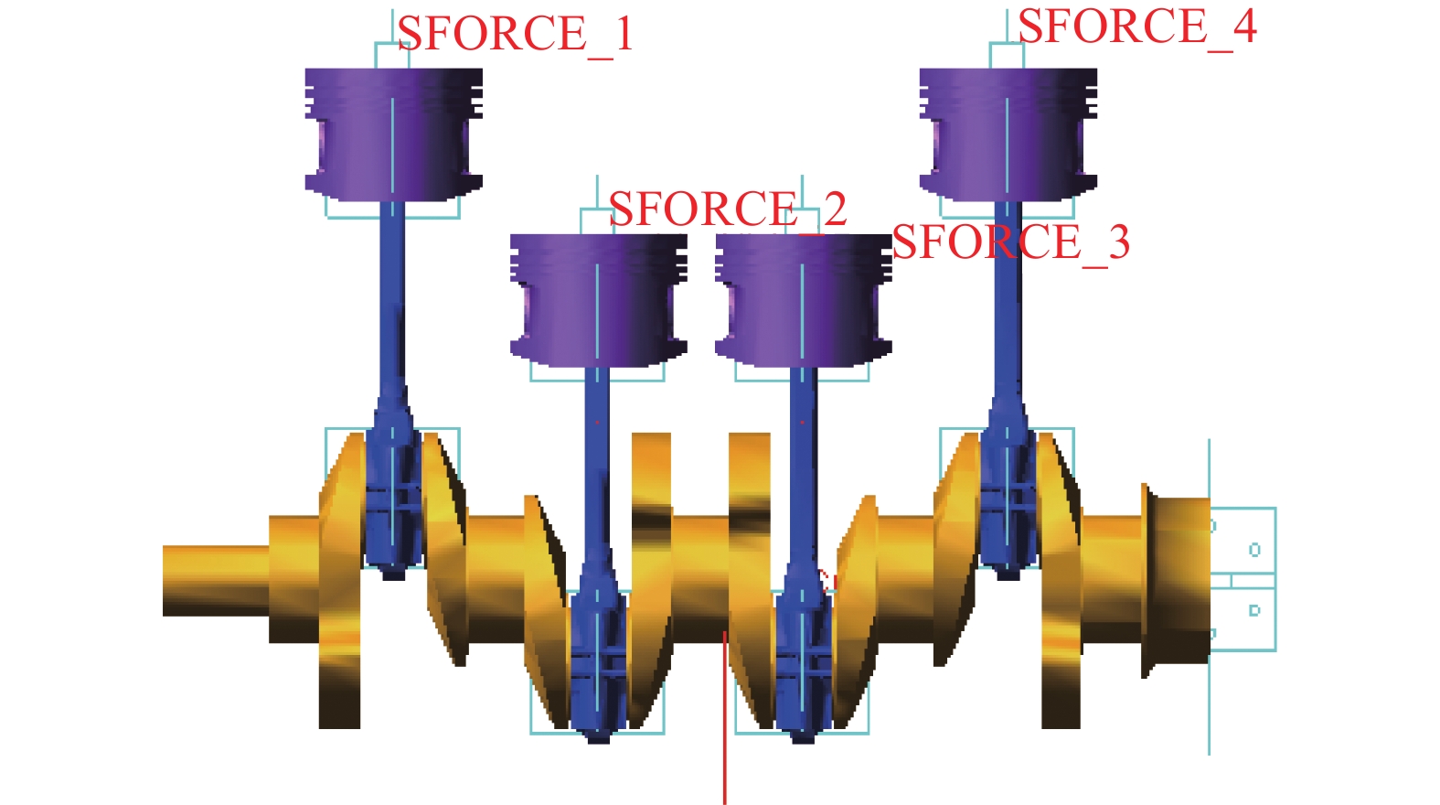
对曲柄连杆机构进行运动仿真需要添加驱动和载荷。添加驱动是在曲轴与地面构成的转动副上添加曲轴转速;施加载荷则是将气缸内燃烧气体的压力分别施加在各气缸活塞的顶部,如图2所示。
气体爆发压力Fg作为主动载荷施加在活塞上表面[6-7]。
式中,D为活塞直径;pg" role="presentation" style="box-sizing: border-box; display: inline; line-height: normal; text-indent: 0px; word-spacing: normal; overflow-wrap: normal; text-wrap: nowrap; float: none; direction: ltr; max-width: none; max-height: none; min-width: 0px; min-height: 0px; border: 0px; padding: 0px; margin: 0px; position: relative;">pg气缸内气体压强;p" role="presentation" style="box-sizing: border-box; display: inline; line-height: normal; text-indent: 0px; word-spacing: normal; overflow-wrap: normal; text-wrap: nowrap; float: none; direction: ltr; max-width: none; max-height: none; min-width: 0px; min-height: 0px; border: 0px; padding: 0px; margin: 0px; position: relative;">p为曲轴箱内气体压强。
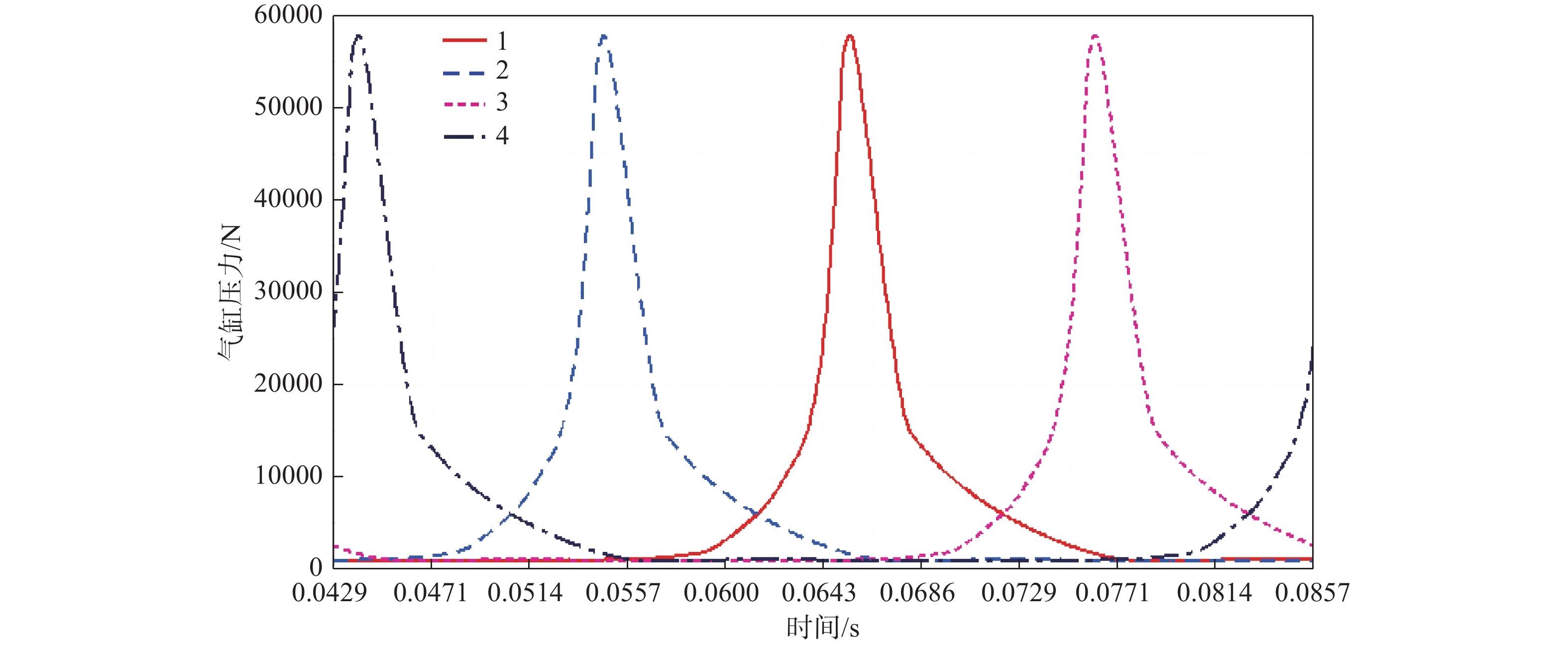
气体爆发压力通过模拟软件AVL-Boot获得[8-9]。压力由AKIMA插值方法获得。利用样条函数AKISPL建立气体压力函数:
其中,第一变量为time,第二变量无,spline_1、spline_2、spline_3、spline_4分别表示4个气缸的气体压力样条曲线。该样条曲线反应的是在曲轴在一定转速下时间与压力的关系。最大转矩工况即曲轴转速为2800 r/min时,4个气缸内的气体压力变化曲线如图2所示。
1.3 曲柄连杆机构动力学分析
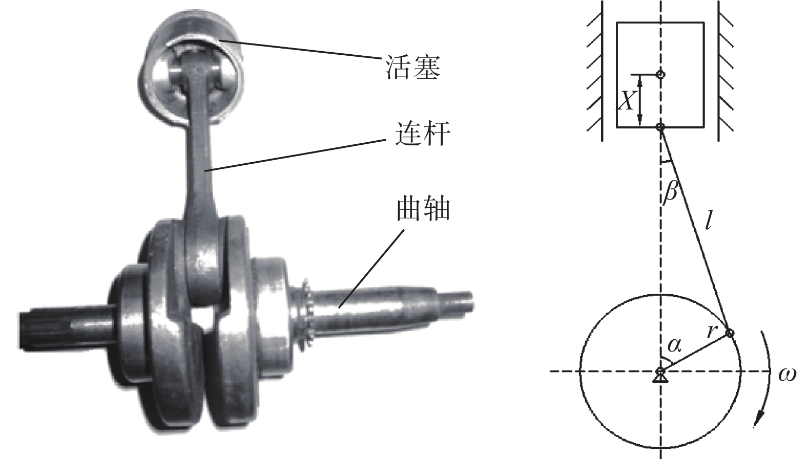
曲柄连杆机构及结构简图如图3所示。图中,l" role="presentation" style="box-sizing: border-box; display: inline; line-height: normal; text-indent: 0px; word-spacing: normal; overflow-wrap: normal; text-wrap: nowrap; float: none; direction: ltr; max-width: none; max-height: none; min-width: 0px; min-height: 0px; border: 0px; padding: 0px; margin: 0px; position: relative;">l为连杆长度;r" role="presentation" style="box-sizing: border-box; display: inline; line-height: normal; text-indent: 0px; word-spacing: normal; overflow-wrap: normal; text-wrap: nowrap; float: none; direction: ltr; max-width: none; max-height: none; min-width: 0px; min-height: 0px; border: 0px; padding: 0px; margin: 0px; position: relative;">r为曲柄半径;α" role="presentation" style="box-sizing: border-box; display: inline; line-height: normal; text-indent: 0px; word-spacing: normal; overflow-wrap: normal; text-wrap: nowrap; float: none; direction: ltr; max-width: none; max-height: none; min-width: 0px; min-height: 0px; border: 0px; padding: 0px; margin: 0px; position: relative;">α为曲轴转角;β" role="presentation" style="box-sizing: border-box; display: inline; line-height: normal; text-indent: 0px; word-spacing: normal; overflow-wrap: normal; text-wrap: nowrap; float: none; direction: ltr; max-width: none; max-height: none; min-width: 0px; min-height: 0px; border: 0px; padding: 0px; margin: 0px; position: relative;">β为连杆摆角;ω" role="presentation" style="box-sizing: border-box; display: inline; line-height: normal; text-indent: 0px; word-spacing: normal; overflow-wrap: normal; text-wrap: nowrap; float: none; direction: ltr; max-width: none; max-height: none; min-width: 0px; min-height: 0px; border: 0px; padding: 0px; margin: 0px; position: relative;">ω为曲轴转速;X" role="presentation" style="box-sizing: border-box; display: inline; line-height: normal; text-indent: 0px; word-spacing: normal; overflow-wrap: normal; text-wrap: nowrap; float: none; direction: ltr; max-width: none; max-height: none; min-width: 0px; min-height: 0px; border: 0px; padding: 0px; margin: 0px; position: relative;">X为活塞位移。
活塞运动方程:
式中,λ" role="presentation" style="box-sizing: border-box; display: inline; line-height: normal; text-indent: 0px; word-spacing: normal; overflow-wrap: normal; text-wrap: nowrap; float: none; direction: ltr; max-width: none; max-height: none; min-width: 0px; min-height: 0px; border: 0px; padding: 0px; margin: 0px; position: relative;">λ为连杆比,λ=rl" role="presentation" style="box-sizing: border-box; display: inline; line-height: normal; text-indent: 0px; word-spacing: normal; overflow-wrap: normal; text-wrap: nowrap; float: none; direction: ltr; max-width: none; max-height: none; min-width: 0px; min-height: 0px; border: 0px; padding: 0px; margin: 0px; position: relative;">λ=rl=0.2348。
连杆既作往复运动也做旋转运动,连杆小头随活塞主要做往复运动,连杆大头随曲轴主要做旋转运动,因此可以把连杆质量分成两部分m1" role="presentation" style="box-sizing: border-box; display: inline; line-height: normal; text-indent: 0px; word-spacing: normal; overflow-wrap: normal; text-wrap: nowrap; float: none; direction: ltr; max-width: none; max-height: none; min-width: 0px; min-height: 0px; border: 0px; padding: 0px; margin: 0px; position: relative;">m1和m2" role="presentation" style="box-sizing: border-box; display: inline; line-height: normal; text-indent: 0px; word-spacing: normal; overflow-wrap: normal; text-wrap: nowrap; float: none; direction: ltr; max-width: none; max-height: none; min-width: 0px; min-height: 0px; border: 0px; padding: 0px; margin: 0px; position: relative;">m2。m1" role="presentation" style="box-sizing: border-box; display: inline; line-height: normal; text-indent: 0px; word-spacing: normal; overflow-wrap: normal; text-wrap: nowrap; float: none; direction: ltr; max-width: none; max-height: none; min-width: 0px; min-height: 0px; border: 0px; padding: 0px; margin: 0px; position: relative;">m1表示主要做往复运动的质量,质心在连杆小端的中心处。m2" role="presentation" style="box-sizing: border-box; display: inline; line-height: normal; text-indent: 0px; word-spacing: normal; overflow-wrap: normal; text-wrap: nowrap; float: none; direction: ltr; max-width: none; max-height: none; min-width: 0px; min-height: 0px; border: 0px; padding: 0px; margin: 0px; position: relative;">m2表示主要做旋转运动的质量,质心在连杆大端的中心处。则:m=m1+m2" role="presentation" style="box-sizing: border-box; display: inline; line-height: normal; text-indent: 0px; word-spacing: normal; overflow-wrap: normal; text-wrap: nowrap; float: none; direction: ltr; max-width: none; max-height: none; min-width: 0px; min-height: 0px; border: 0px; padding: 0px; margin: 0px; position: relative;">m=m1+m2;mj=mh+m1" role="presentation" style="box-sizing: border-box; display: inline; line-height: normal; text-indent: 0px; word-spacing: normal; overflow-wrap: normal; text-wrap: nowrap; float: none; direction: ltr; max-width: none; max-height: none; min-width: 0px; min-height: 0px; border: 0px; padding: 0px; margin: 0px; position: relative;">mj=mh+m1;mr=mk+m2" role="presentation" style="box-sizing: border-box; display: inline; line-height: normal; text-indent: 0px; word-spacing: normal; overflow-wrap: normal; text-wrap: nowrap; float: none; direction: ltr; max-width: none; max-height: none; min-width: 0px; min-height: 0px; border: 0px; padding: 0px; margin: 0px; position: relative;">mr=mk+m2。mh" role="presentation" style="box-sizing: border-box; display: inline; line-height: normal; text-indent: 0px; word-spacing: normal; overflow-wrap: normal; text-wrap: nowrap; float: none; direction: ltr; max-width: none; max-height: none; min-width: 0px; min-height: 0px; border: 0px; padding: 0px; margin: 0px; position: relative;">mh为活塞组质量;mk" role="presentation" style="box-sizing: border-box; display: inline; line-height: normal; text-indent: 0px; word-spacing: normal; overflow-wrap: normal; text-wrap: nowrap; float: none; direction: ltr; max-width: none; max-height: none; min-width: 0px; min-height: 0px; border: 0px; padding: 0px; margin: 0px; position: relative;">mk为曲轴组质量;mj" role="presentation" style="box-sizing: border-box; display: inline; line-height: normal; text-indent: 0px; word-spacing: normal; overflow-wrap: normal; text-wrap: nowrap; float: none; direction: ltr; max-width: none; max-height: none; min-width: 0px; min-height: 0px; border: 0px; padding: 0px; margin: 0px; position: relative;">mj为往复运动部分的转换质量;mr" role="presentation" style="box-sizing: border-box; display: inline; line-height: normal; text-indent: 0px; word-spacing: normal; overflow-wrap: normal; text-wrap: nowrap; float: none; direction: ltr; max-width: none; max-height: none; min-width: 0px; min-height: 0px; border: 0px; padding: 0px; margin: 0px; position: relative;">mr为旋转运动部分的转换质量。
活塞组的往复惯性力:
式中,负号表示往复惯性力的方向与加速度方向相反。
曲轴组的旋转惯性力:
式中,负号表示旋转惯性力的方向沿曲柄销半径向外。
作用在连杆上的力:
2. 理论计算与ADAMS仿真结果对比分析
以连杆1为例,最大转矩工况下曲轴转速为2800 r/min,压缩冲程终止,活塞运动至上止点,此时缸内气体爆发压力最大,连杆会承受最大压缩载荷;计算可知当气体作用力最大时,Fg" role="presentation" style="box-sizing: border-box; display: inline; line-height: normal; text-indent: 0px; word-spacing: normal; overflow-wrap: normal; text-wrap: nowrap; float: none; direction: ltr; max-width: none; max-height: none; min-width: 0px; min-height: 0px; border: 0px; padding: 0px; margin: 0px; position: relative;">Fg=57885 N,α" role="presentation" style="box-sizing: border-box; display: inline; line-height: normal; text-indent: 0px; word-spacing: normal; overflow-wrap: normal; text-wrap: nowrap; float: none; direction: ltr; max-width: none; max-height: none; min-width: 0px; min-height: 0px; border: 0px; padding: 0px; margin: 0px; position: relative;">α=18.48°,β" role="presentation" style="box-sizing: border-box; display: inline; line-height: normal; text-indent: 0px; word-spacing: normal; overflow-wrap: normal; text-wrap: nowrap; float: none; direction: ltr; max-width: none; max-height: none; min-width: 0px; min-height: 0px; border: 0px; padding: 0px; margin: 0px; position: relative;">β=4.27°,作用在连杆上的压力为Fk" role="presentation" style="box-sizing: border-box; display: inline; line-height: normal; text-indent: 0px; word-spacing: normal; overflow-wrap: normal; text-wrap: nowrap; float: none; direction: ltr; max-width: none; max-height: none; min-width: 0px; min-height: 0px; border: 0px; padding: 0px; margin: 0px; position: relative;">Fk=56141 N。
最高转速工况下曲轴转速5300 r/min,排气冲程终止,活塞运动至上止点时,此时连杆往复惯性力最大,连杆会承受最大拉伸载荷;计算可知当往复惯性力最大时,Fg" role="presentation" style="box-sizing: border-box; display: inline; line-height: normal; text-indent: 0px; word-spacing: normal; overflow-wrap: normal; text-wrap: nowrap; float: none; direction: ltr; max-width: none; max-height: none; min-width: 0px; min-height: 0px; border: 0px; padding: 0px; margin: 0px; position: relative;">Fg=1954 N,α" role="presentation" style="box-sizing: border-box; display: inline; line-height: normal; text-indent: 0px; word-spacing: normal; overflow-wrap: normal; text-wrap: nowrap; float: none; direction: ltr; max-width: none; max-height: none; min-width: 0px; min-height: 0px; border: 0px; padding: 0px; margin: 0px; position: relative;">α=1.86°,β" role="presentation" style="box-sizing: border-box; display: inline; line-height: normal; text-indent: 0px; word-spacing: normal; overflow-wrap: normal; text-wrap: nowrap; float: none; direction: ltr; max-width: none; max-height: none; min-width: 0px; min-height: 0px; border: 0px; padding: 0px; margin: 0px; position: relative;">β=0.44°,作用在连杆上的拉力为Fk" role="presentation" style="box-sizing: border-box; display: inline; line-height: normal; text-indent: 0px; word-spacing: normal; overflow-wrap: normal; text-wrap: nowrap; float: none; direction: ltr; max-width: none; max-height: none; min-width: 0px; min-height: 0px; border: 0px; padding: 0px; margin: 0px; position: relative;">Fk=4482 N。
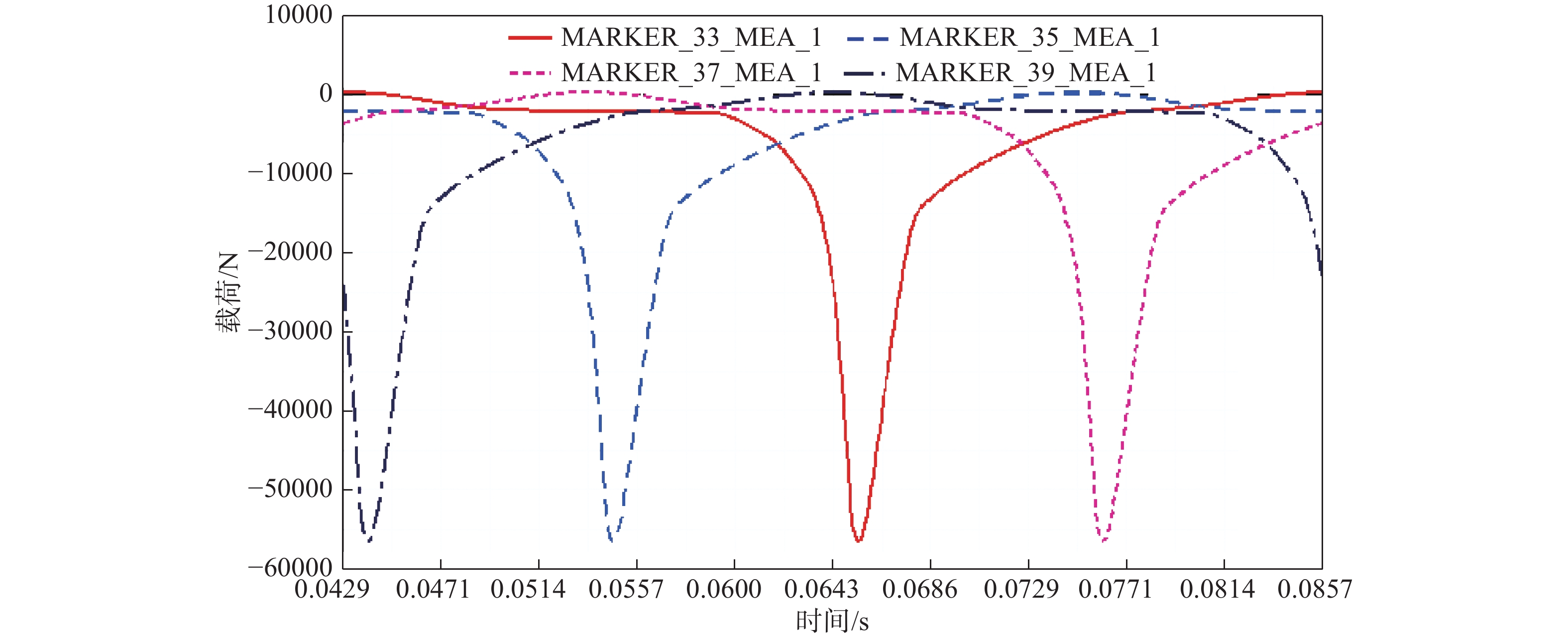
在最大转矩工况下,稳态仿真两个工作循环,取第二个工作循环进行分析。连杆小头端受力变化曲线如图4所示。
最大转矩工况下,连杆小头端主要承受沿杆身方向的压缩载荷,对比发现4个气缸连杆承受最大压缩载荷时刻均为点火瞬间,且对于连杆1而言,通过ADAMS仿真得到其最大压缩载荷值为56491 N,各连杆小头端受力情况如表2所示。
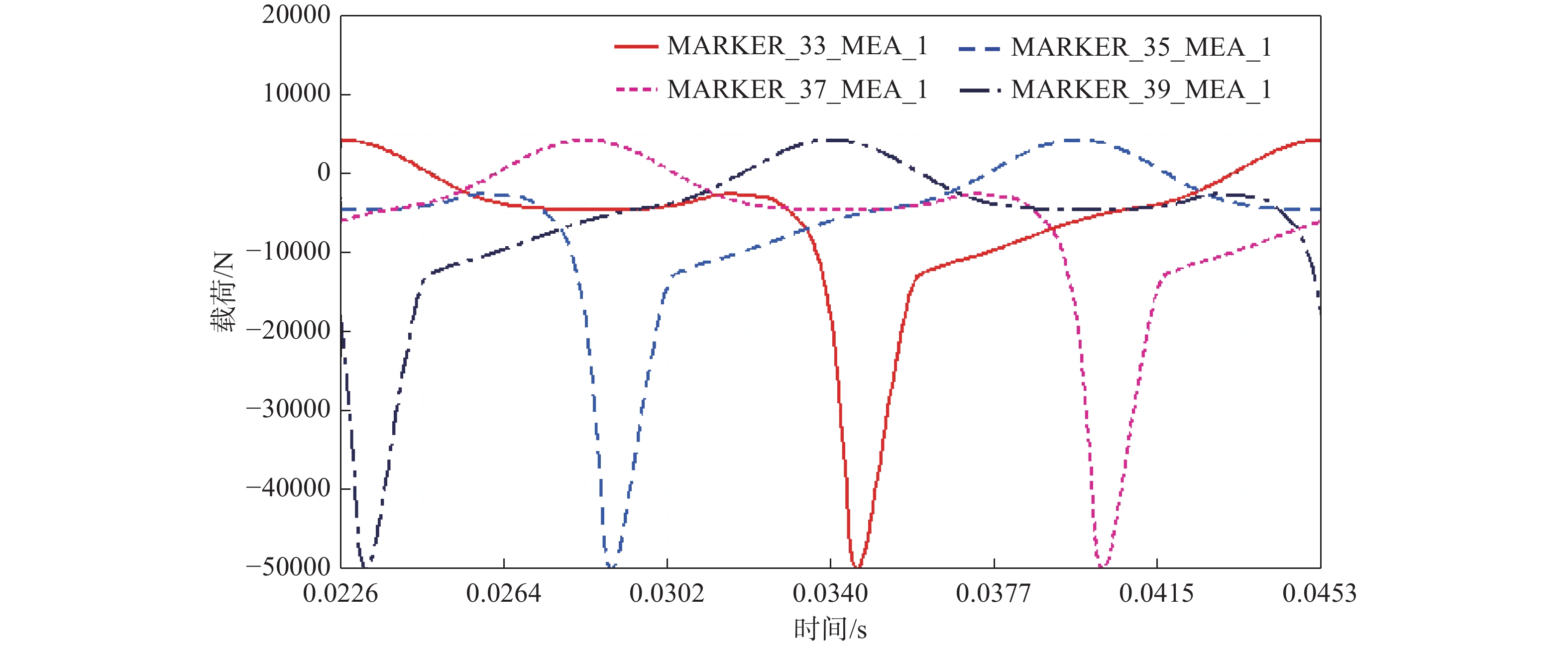
在最大转速工况下稳态仿真两个工作循环,取第二个工作循环进行分析。连杆小头端受力变化曲线如图5所示。
最大转速工况下,连杆小头主要承受沿杆身方向的压缩和拉伸载荷,且4个气缸连杆承受最大压缩载荷时刻均为点火瞬间,但最大值与最大转矩工况下相比较小。由于活塞往复惯性力的影响连杆小头在上止点处会承受较大拉力,通过ADAMS仿真得到连杆1最大拉伸载荷值为4399 N,各连杆小头端受力情况如表3所示。
对比分析:(1)最大转矩工况下,对于连杆1,ADAMS仿真得到其最大压缩载荷值与理论计算得到的最大压缩载荷值对比见表4。其值误差为0.6%,小于5%,证明了仿真方法的合理性。(2)最大转速工况下,通过ADAMS仿真得到连杆1最大拉伸载荷值与理论计算所得最大拉伸载荷值见表4。其值误差为1.89%,小于5%。证明了仿真方法的合理性[10]。
3. 工程实践教学
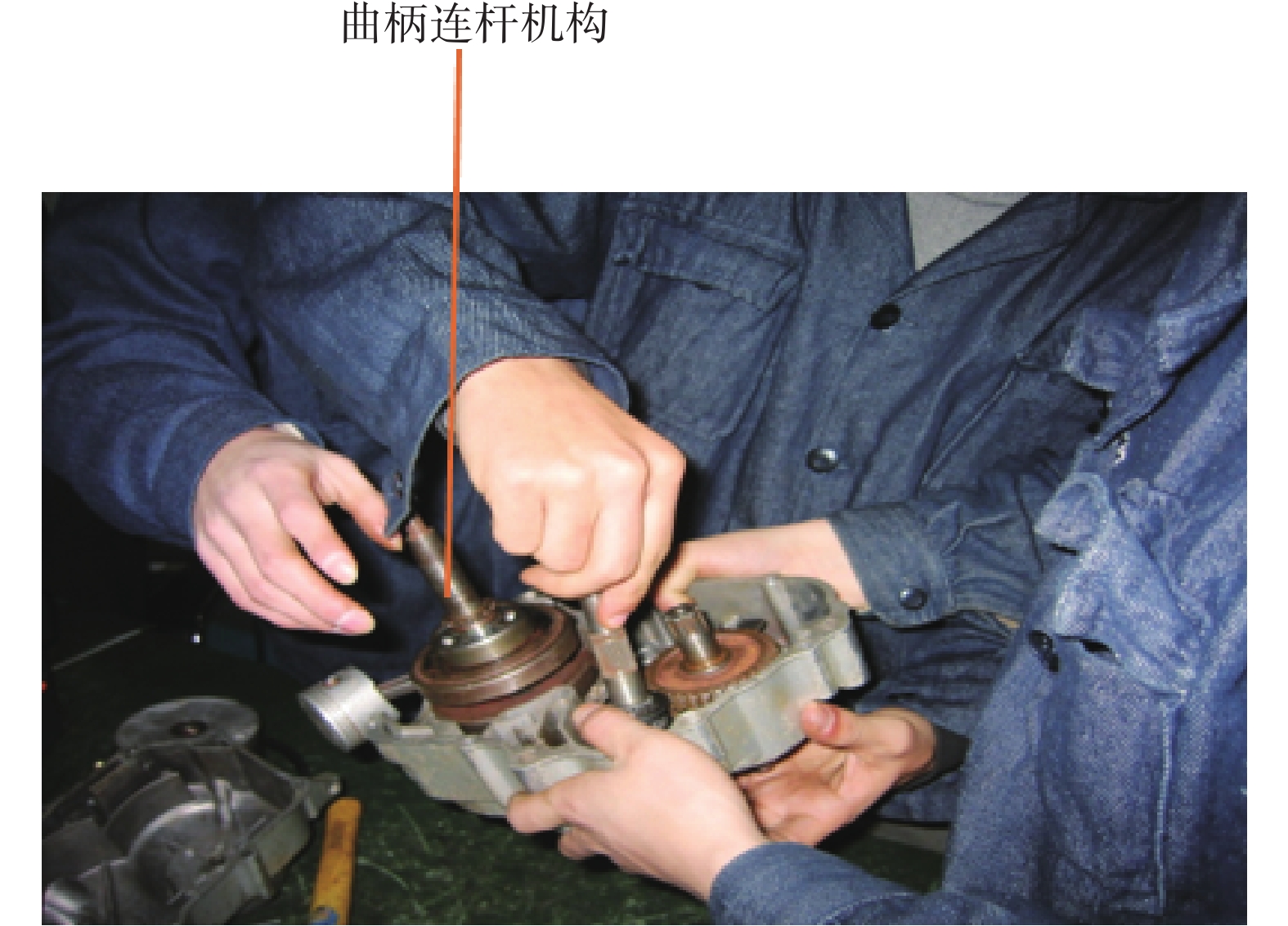
通过发动机拆装工程实践教学学习曲柄连杆机构,如图6所示,了解真实的机器设备,学习曲柄连杆机构的功用、结构组成和运动方式,如图7所示。
曲柄连杆机构由机体组、活塞连杆组、曲轴飞轮组三部分组成。曲柄连杆机构的功用是将活塞的往复运动转变为曲轴的旋转运动,同时将作用于活塞上的力传递到曲轴对外输出转矩,驱动汽车车轮转动,即完成能量转换、传递动力、改变运动形式。
4. 结束语
(1)通过ADAMS仿真得到连杆在一个工作循环内的受力变化曲线,对于连杆1而言在最大转矩工况下连杆小头承受最大压缩载荷为56491 N,最大转速工况下连杆小头承受最大拉伸载荷为4399 N。且仿真得到的值与理论计算值误差在5%以内,证明仿真方法的合理性。
(2)多体动力学分析可以为有限元分析提供载荷边界条件,通过对最大转矩工况和最大转速工况下连杆应力分析,可以得到连杆所承受的最大压缩载荷和最大拉伸载荷,为连杆的结构设计和改造提供了理论依据。
(3)通过发动机拆装实践教学,学生可以直接获得直观真实的工程机构知识、培养了工程意识与工程实践能力。实践教学与现代设计手段相结合,通过刚体动力学仿真,可以使学生对曲柄连杆机构的受力情况掌握的更加透彻和深入,为培养机构、构件设计分析能力奠定基础。
来源--金属世界


 下载:
下载: